K9 Battery Charger
I like to play chess. Not the serious game, but the fun version called Simultaneous Speed Chess or Bug House. Chess clocks are needed to play. I have built many clocks. The item that fails is either a push button or the battery. I have found some excellent buttons, but have yet to find a reliable battery. The clocks are an old design with LED displays that requires about 200ma operating current. I have tried most battery technologies and designed numerous chargers. Via trials, I discovered a very simple charger that I which to share.
Most battery chargers are designed for a specific battery. They can be extremely complex. Some use a micro computer for control. This page presents simple chargers that can be used to charge any battery. The circuits are not designed for fast charging. The emphasis is on simplicity.
How Simple?
Is four components plus cords too much?
Battery
Charging Fundamentals
A battery is classified by the chemical type, NiCad, Nimh, Lead Acid, or Li-Ion. Each type has a cell voltage, 1.2 volts for NiCad and Nimh, 2 volts for Lead Acid, and 3.4 volts for Li-Ion. Each cell has a capacity (C) in Ahrs. C is current that the cell can supply for 1 hour. I want the chess clocks to run for at least 5 hours. This implies a C of > 1Ahr.
A battery can have multiple cells connected in series and parallel to provide the desired voltage and capacity. The chess clock needs 4 to 6 volts. I have tried series connections of 4 NiCad cells, 4 Nimh cells, 3 lead acid cells, and two Li-Ion cells, to create the voltage.
When charging, the charger energy is absorbed by the battery. When full, the charger energy heats the battery. To prevent overheating, the charge current must be reduced to a small value when the battery is full. Full is difficult to detect.
Manufactures have specific recommendations for charging. They can be very complex.
Since batteries are not robust, it is imperative to follow the recommendations.
- Maximum charge current.
The maximum charge current is often the C rating in amps. Easiest way to comply is to use a wimpy charger.
To charge chess clocks I use a power supply with a 1 amp rating.
- Cut Off
When the battery is full, the charge current must be reduced to a trickle level, typically C/10 or less.
I often design the charger for a C/20 current. This implies a 24 hour charge time.
For Lead Acid and Li-Ion cells the manufacturer recommends a current limited constant voltage charger. You can use a bench supply with a current rating less than the maximum charge current to charge these batteries. Just set the bench supply to the recommended charge voltage. The battery is fully charged when the charge current goes to zero. No cut-off circuit is needed.
If the battery has multiple cells, charging becomes more difficult. If the cells are not precisely matched, one cell will become full before the others. If you continue charging, the full cell can heat up. If you stop charging, some cells will not be full.
On this web page, I will describe some simple chargers that I have built. None are fast charger. One is a simple modification to an AC adapter.
Let’s look at a typical consumer charger. The equivalent circuit is shown below:
Voltage mode charger
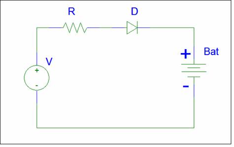
The Diode D prevents the battery from discharging.
The DC Voltage V is selected to be greater than the
The source resistance R limits the charge current. The maximum current is V/R.
The charge current decreases as the battery voltage increases.
The full charge current = (V-BAT)/R provides a small trickle current.
The maximum and trickle currents must be carefully selected to meet the battery requirement.
The DC voltage is created by an AC adapter. The slope resistance may be the source impedance of the adapter.
The main problem with this approach is the precision required.
I have a collection of AC adapters, but can never find the correct adapter.
Most consumer chargers lack the circuitry needed to detect a full charge. They switch to a lower charge before the battery is full. To get a full charge you need to leave the battery connected much longer than the claimed charge time.
An alternative is to charge the battery with the trickle current. With the small trickle current, there is no need for a complex cut-off circuit.
Expect a 24 hour charge time.
You can remove the voltage dependency if you use a constant current charger.
This charger will be able to charge a variety of batteries. If you have one, two, or more cells you can use the same charger.
In the above circuit if V is much larger than the battery voltage, the charge current is almost constant.
Current mode charger
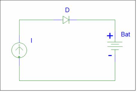
Instead of a voltage source, the equivalent circuit is now a current source.
For safe charging the current should be < C/10.
You can set the charge current to C/20 and leave the battery connected for 24 hours.
Dc current sources are inefficient. Let’s look at an example.
You want to charge a 9 volt battery with a capacity of 150mAhr.
To be safe we select a charge current of 10ma.
For V we want to use the rectified line voltage = 170 volts.
The current limit resistor = 170 / 0.01 = 17 K ohm.
The power dissipation in this resistor is 170 * 170 / 17 K = 1.7 watts.
The power supplied to the battery is 9V * 10ma = 0.09 watts.
For a 100ma charge current, the resistor is 1.7K and the power increases to 17 watts.
The problem with a DC current source is the power dissipation of the current limit resistor.
If you switch to AC, you can create the current limit impedance via a capacitor.
An AC capacitor has almost no power dissipation.
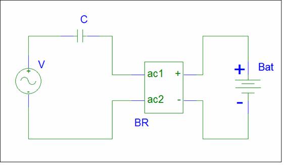
In the circuit above, V is a large AC voltage, possibly the line voltage.
The Bridge rectifier and capacitor must be rated for the rectified line voltage and charge current.
The capacitor C limits the ac current I to V/Z(C) . For a 120 volt 60hz source the current is about 40ma/uF.
C must be a non-polar capacitor with a voltage rating greater than the peak AC voltage. For a 120 volt line, C needs to have at least a 200 volt rating.
Do not connect two electrolytic capacitors in series to create the AC capacitor. Electrolytics can have a large series resistance.
Use a film capacitor.
With a rectifier and capacitor, you can build a two component battery charger. There is a problem.
Warning
No Isolation
The above circuit lacks galvanic isolation and can provide hazardous voltages on the interface.
No start up surge current limit
The circuit lacks start up current limiting. Until C is charged, large currents can flow.
Shock hazard
The capacitor will retain whatever voltage it had when disconnected.
If you touch the AC plug, you may get shocked.
AC film capacitors have very low leakage and are excellent at retaining a charge.
You need to add a large value resistor in parallel to create leakage.
Let’s design some AC current mode chargers.
Charger Cable
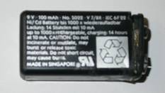
Design a charger for a 9 Volt Nimh battery.
The specs on the battery are:
8.4 V DC.
Capacity 150mAh
Charge 14 hrs at 14mA max
For the charger cable, I chose a non-isolated design. A 10ma charge current appears appropriate. The nominal rule of 40ma/uf suggests a 0.25uf capacitor. I found a 0.261uf film capacitor in my collection. To limit start up surges I used a 100 ohm power resistor. The bridge rectifier is rated for 1A 400V, total overkill.
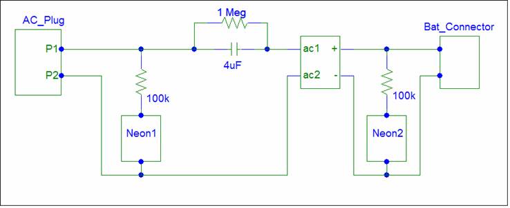
The schematic is shown below. It is flipped to match the picture.

10ma is a suitable current for an LED. I could not resist the opportunity to enhance the design. The cap in parallel with the LED was added to absorb any start up surge current. The LED is on when current is flowing. The 9 volt connector after use spread out and can fail to make a connection. The LED provides a handy indication.
If you notice that the LED is not
lit, unplug the charger, tighten the clips, and reconnect the charger.
Never make connections while
connected to the AC line.
Testing revealed that the charge current is 10.67ma.
The component values are not critical.
Some 9 volt batteries have only 6 cells. This charger is suitable for both 6 and 7 cell batteries.
A picture of the prototype is shown below:
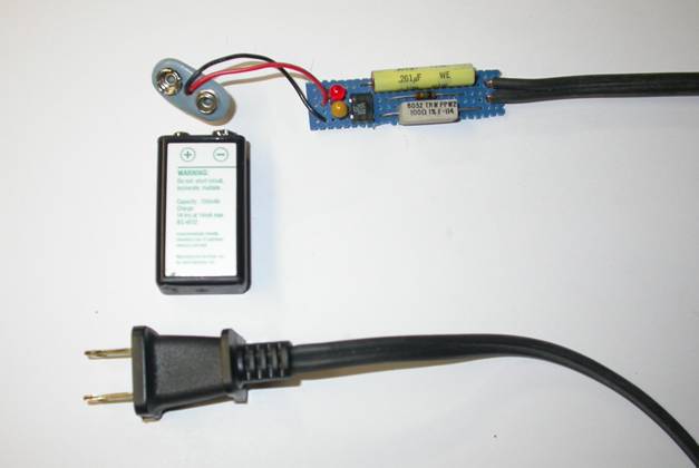
The circuit is constructed on a proto board. To avoid accidental contact, you need to seal the circuit in shrink wrap or electrical tape. If you want to show the components, use clear hot glue.
Since the circuit lacks isolation,
always connect the battery before plugging the AC cord into an outlet.
Disconnect the AC cord before disconnecting
the battery.
Do not touch the circuit while
charging.
Without a load, the circuit can have
170 volts on the battery terminals, more than enough voltage to shock anyone.
For 9 volt NiCad batteries the capacity and charge rate is lower. You may need to decrease the capacitor value to avoid the battery shown below.
If you plan to leave the charger connected continuously, you need to reduce the charge current.
Trickle Charger
Nimh batteries have a high self discharge rate. If you want to use one in a smoke alarm, you will need to provide a small trickle charge.

In this circuit the capacitor is connected to the low voltage side of the transformer. This allows a lower voltage capacitor to be used. No leakage resistor is needed. All points on the secondary side are safe.
The circuit created a 2ma trickle charge. For larger values, increase the capacitor value or use a capacitor on the line side.
A picture of the trickle charger is shown below.
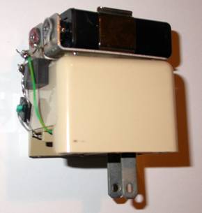
The battery is mounted on the back of an AC adapter.
The adapter provides isolation. No protection is needed.
The charge rate of the original design was too low. I added a 0.1 cap (green).
Nicad Charger
The charger cable provides 10ma to any load. You can use it to charge any Nicad battery pack. The pack voltage does not matter. The problem is the charge time. If a pack has a 1500maHr capacity, it will take a week to charge an empty battery. Great excuse if you want to postpone projects. If we increase the charge rate to 150ma, the charge time is about 10hrs, over night.
To get the higher charge current, the capacitor value is increased to 4uF. The 4uF capacitor can store a larger charge than the previous 0.261uF capacitor. Don’t forget the bleed off resistor.
This charger current is too large for an LED. So instead of a current monitor, the above circuit uses Neon bulbs to monitor the input and output voltages. Need to find a use for those old components. The prototype is shown below.
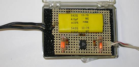
The parts are packaged in a sample case. I used 120k instead of 100k resistors for the Neons.
Neon 1 monitors the AC line voltage. When the adapter is connected to AC, both bars become lit.
Neon 2 monitors the DC output voltage. The DC voltage will light only one bar when high voltage is on the output.
During charging, Neon1 is on and Neon 2 is off.
If both are lit, the battery is not
connected. Unplug the AC cord, reconnect
the battery, plug in the AC cord, and try again.
This circuit lacks start up current limiting. This can be beneficial. Nicad batteries occasionally develop a small internal short. A surge may blow out the short. There is no guarantee. It depends on when the AC connection occurs. You can test your luck. Murphy states that the surge will only occur when you don’t want it.
A safer isolated charger is described below;

A resistor is added across C to create leakage.
A transformer T is added to provide isolation and limit the start up current.
The transformer can reduce the maximum output voltage to a safe value.
You can connect a voltmeter across the battery.
The DC voltage shows the charge.
The AC voltage shows Battery Equivalent Series Resistance, which is an indication of health.
Instead of building this circuit, a simpler approach is to find an AC adapter whose output ratings in current and voltage exceed the desired values. An ideal candidate should have a large DC output voltage and a current rating equal to the desired charger current.
The DC output voltage must be much larger than the battery voltage to create a current source.
The DC output rating must greater than the charger current to avoiding stressing adapter components.
I found a 48 volt DC, 200ma adapter. After opening the case with a hack saw, I removed the filter capacitors and measured the transformer inductances to create the simulation model shown below:

V1 is a 60 hertz AC source. V3 is the battery. TX1 is the adapter transformer. The diodes are modeled as 1N4002 parts.
After a few trials, a 1.5uF capacitor value was selected. The simulated charger output current is shown below.
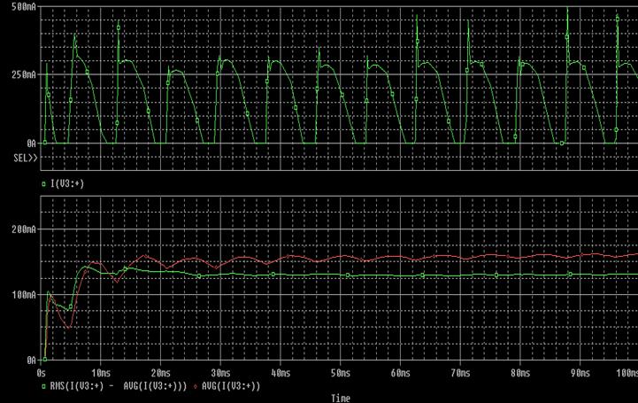
The top trace shows the pulsating current applied to the battery.
The trace below shows the AC (green) and DC (red) components of the charger current.
Here’s a picture of the modified adapter.
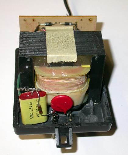
I disconnected the wire connecting the transformer to one side of the line and wired a 1.54uF cap plus bleed resistor in series.
After I put the cover back, this sloppy modification will be hidden.
AC Charging
The technique employed on this page uses AC charging. The charging current contains both an AC and a DC component. The AC component is primarily 120 hertz, twice the line frequency. Only the DC component adds charge to the battery.
For fast high current chargers, the AC component generates heat and should be eliminated.
For the low current chargers described on this page, the power wasted is small. There are benefits to AC charging.
The first benefit is that it provides any easy way to the measure the battery Equivalent Series Resistance (ESR). Just connect a volt meter at the battery terminals. The AC voltage is created by the ESR of the battery.
The second benefit is that the pulsating current and high voltage can stimulate the battery. Lead Acid batteries can dry up and refuse to accept a charge from the recommended constant voltage charger. The AC charger will apply a pulsating high voltage to force current into the battery.
I have been able to rejuvenate some batteries with the AC charger. You need to shake up those Battery Ions.
Battery Testing
The best way to test any battery is to determine the capacity. You need to fully charge the battery. Connect the load and measure the time to the discharge cut off point. This takes a lot of time.
Just measuring the voltage of a battery is not a good test. Many batteries will show a full charge voltage, even when they are bad or almost empty. Adding a load will provide a better indication. Just connect a resistor in parallel with the meter. I made a 100 ohm load that I can connect across the meter terminals.
A better test is to measure the battery ESR. Connect the AC charger and measure the AC voltage at the battery terminal.
The ratio of voltage / current = ESR. ESR is a low number, typically much less than 1 ohm. ESR will vary with the battery size. Big ones are equivalent to small batteries in parallel and have lower ESR.
The isolated AC charger has an AC current of about 120ma. With an ESR of 1 ohm, this creates a 120mV reading on the AC meter.
If you measure > 100mv, you may have a bad battery.
Some AC meters measure the RMS value which includes both the AC and DC components. You don’t want this. You could add a series capacitor to remove the DC component, but this will complicate the test set up. I prefer to use a meter that allows easy switching between AC and DC. The DC value indicates charge, the AC value indicates health.
The current mode chargers can have a
large voltage at the output. Always make
all connections before connecting to the AC line and turn the power off after
the test. The chargers are not intended
to be test tools that can be used as probes.
I use an outlet strip to provide an easy way to switch the power. A lamp plugged into the outlet strip provides
a warning that the charger is on.
Conclusion
With a web search, you can find many
A current charger mode charger removes the voltage dependency. You can charge any number of cells in series.
The disadvantage is the high output voltage. Safety precautions are needed.
Full detection is not necessary if the charge current is the trickle current. A long charge times is the tradeoff.
There is nothing precise in these designs. Feel free to modify the design. Put some of those obsolete components to a good use.
Disclaimer
The charger designs presented here can be
dangerous. They are intended for
hobbyists that are skilled in handling high voltages and non-isolated circuits.
If anything goes wrong, it is entirely your fault.
© Dieter Knollman 2007
Best viewed with Firefox.
The pictures may not be visible in Internet Explorer. I don’t know why. This Webpage was created with MS Word.
I clicked Insert Picture to add the pictures. The code that Word created may be considered malicious by IE.
Check out my other Web pages:
Powered by WebRing.