Headphone Amplifier
This web page presents the design of a portable Headphone Amplifier. A prototype is shown below. The Schematic is at the end of this page.

What distinguishes this design is not what’s included, but what is not included. Common audio components such as: an input volume control, input caps, large output capacitors, and bias circuitry are missing. The resulting design creates optimum audio performance.
This Web page discusses circuit tradeoffs. I found a lot of bad ideas and lots of marketing hype when searching the web. I hope to clarify some design alternatives.
Most web page authors assume that visitors have too much money. They offer many items for sale to solve this problem.
I can’t help. There is nothing for sale here. I do provide links to some excellent free programs. If you like one, you may send a donation to the author.
Problem
I bought a new MP3 player. This player uses a single AAA battery.
With the level set to about 80%, the output volume of the new player is sufficient, but not as clear as the two cell player.
Compared to the two cell player, the sound is muddy.
Can a single battery provide sufficient output?
Measurement of the single cell player at full volume yielded a peak output level of 0.4 volts into a headphone (32 ohm) load. This is 0.0025 watts, or 2.5mW (milli-watts). Audiophiles like to measure output in watts, not milli-watts.
The two cell player has a peak output of 0.8 volts or 10mW. Better, but not what an Audiophile may want.
The two cell player does sound better with my low distortion headphones.
A search of the Web indicated that Specifications for most MP3 players failed to list the output level. I did find one single cell player that listed 10mW output, i.e. 5mW per channel. The discrepancy can be that I assumed a sine wave form factor and used a rechargeable battery. With lots of clipping you may get 5mW per channel or 10mw output from a single cell player.
A single cell player has a 1.5 volt supply which needs to supply the peak to peak output. If you double the peak level and leave a little headroom for the output, 2.5mW is probably the best you can hope for.
I suspect that one problem with the single cell player is clipping.
Audio can have large peaks. Many players can’t handle the audio peaks and clip at the maximum output. This creates harmonic distortion, which may be tolerable. It simply makes one instrument sound like a different instrument. If you are a musician or an audiophile, you can find this very annoying.
The second factor is the headphones. They may be creating the clipping. Unless you have low distortion headphones, an amplifier may not help. Headphone clipping is not as hard as amplifier clipping, hence more tolerable. Look for low distortion headphones.
The third factor is the source. MP3 files are digital. This simply means that you can make copies without altering the sound quality. Digital says nothing about the quality. The quality can be excellent or awful. There are a lot of very bad MP3 files. The fault is in the encoder, not the MP3 format. For the best audio quality use CDex to rip your CDs with the LAME encoder set to the highest quality level. The program is free and easy to use.
Many MP3 files are encoded with clipping. You can use Mp3Gain to adjust the levels of your Mp3 files. This program is also free and easy to use. It can create a constant volume level for all your MP3 files, without re-sampling. All encoding abnormalities are preserved.
Warning: An Amplifier and Headset, that can reproduce Audio peaks without clipping, can damage your hearing.
What did you say?
For best audio, you need all three, a player with sufficient output, low distortion headphones, and good source files.
I have low distortion headphones and gain adjusted high
quality MP3 files. I need an amplifier
to boost the player output.
Build or Buy
An internet search will yield many sources. Commercial amps cost > $100. Homemade amps can be very inexpensive, if you have the time and a good collection of parts. If you value your time, the Commercial amps are a bargain. I prefer the build it option. It let’s me optimize the amplifier for a specific application.
Even if you don’t want to build the circuit, read the page to find features to look for. For example, if the amp uses two AAA batteries, pass. Also avoid amps with large output caps. I could not find a good amplifier.
Price is not a good indicator of quality. If you have a bad design, you need to charge more since you won’t be selling as many. Don’t worry, there is always some audiophile that has too much money and wants to flaunt his ignorance.
Before inventing a new circuit, I made a search of existing designs to see what’s possible. I found most of the Web designs lacking. Some have no chance of working. Marketing hype has replaced good design.
I’ll discuss the circuit options and show potential pitfalls.
The new design is intended to be the best possible from an electrical point of view.
The key to a good design is to avoid mistakes and use some good judgment.
Requirements
The Web search indicated that a 50mW output would be desirable. This is a 1 volt RMS output that matches the peak headphone level.
For a 32 ohm load, 50mW is a peak output of 1.8 volts. The peak to peak voltage is 3.6 volts.
If you add a little for headroom, a power source of 5 volts minimum is needed. With alkaline batteries, you’ll need at least 4.
The peak amp output current is 1.8 / 32 = 56ma. This assumes that the headphones are 32 ohm at all frequencies.
Look for a minimum 80ma drive capability to handle impedance variations.
The unit should be portable with an internal battery. I don’t need a studio amplifier.
If you walk a lot, rechargeable batteries are a must have option.
A 10 hour battery time is sufficient.
The amplifier should not add noticeable distortion to the audio.
Color only matters to iPod users. Paint it pink.
For true
audiophiles, I recommend a tube amplifier with a DC to AC Inverter and a 12
volt marine battery.
If you can drag
this along, you will burn lots of calories on your walk.
For the rest of us,
weights are safer than high voltage electronics.
Circuit Configuration
Discrete circuits
allow the operating point to be optimized for minimal noise figure. For the large input signal level from the MP3
player, this is not needed.
Most Op-Amps
can’t drive a 32 ohm load. Look
for an op-amp with 80ma output drive and a 5 volt supply.
Some op-amps claim rail to rail output. Don’t be fooled. They can only achieve this with no load.
Some “single supply” op-amps claim rail to rail input. Ignore this. Op-amps don’t like the supply rails.
If you plan to
build it, look for a DIP package. This
implies an obsolete part.
If you can handle
surface mount parts, look at DSL Op-amps such as the TS613ID or AD45048 .
Avoid integrated
solutions. Op-amps have lots of gain to
make the circuit response equal to the ideal response. The ideal response for a non-inverting
amplifier is 1 + RF/RI. You want RF and
RI to be high quality resistors. Integrated
resistors do not qualify.
If the IC has
anything connected to the + or – op-amp inputs, look for another part.
Amplifier Design
For the design a TS925
op-amp from my junk pile was chosen. The
TS922 is a smaller version, but not in my collection.
Don’t be
confused by the ST marketing hype, the part is barely adequate. You may find better choices.
What gain should the amplifier have?
Mp3 players have a Digital to Analog Converter (DAC) in the output. The DAC has a limited range. For best audio quality you want to use the entire range, i.e. you want the peak MP3 player output level to create the peak amplifier output level. A single cell player will have a 0.4Vpeak output. A 50mW amplifier will have a 1.8Vpeak output. Hence the gain is 1.8/0.4 = 4.5.
If the gain is higher, the player DAC will only use the lower level output codes. The smallest steps (sampling noise) will be amplified more than needed. Sampling noise is very bad. Don’t set the gain too high.
If the gain is much lower, there is a danger of clipping.
Volume Control?
Avoid using an input volume control. They tend to be noisy and increase distortion.
With an input volume control, the amplifier needs more gain to compensate for the input control attenuation.
For example, if the volume control is linear and set at the middle, the input signal is cut in half. The amplifier gain needs to be doubled.
This will cut the excess gain in half. The resulting design will have twice the distortion and half the bandwidth.
If you want to adjust a gain, replace a resistor. The new value is easily obtained via the Shadow's Design procedure. You can have different gains for the right and left channels to compensate for your hearing.
For best performance set the gain to the minimum required.
Inverting or Non-Inverting?
Many Integrated designs use an Inverting Amplifier configuration. This saves pins, but sacrifices performance.
A Non-Inverting Amplifier will have less noise and better bandwidth. See Daisy .
Many audio “experts” don’t know this and continue to use Inverting designs.
Amplifier Configurations
There are many possibilities. I’ll discuss some of the options I found.
The TS925 datasheet shows a sample circuit.

This circuit is typical of what you can find with a web search. The circuit has some bad points:
- Supply is two LR6 batteries. We know at least 4 are needed.
- The Phantom Ground circuit is not needed. Use the midpoint of the batteries.
- The input volume control is not needed.
- Input is AC coupled. The input caps are not needed.
- Output is AC coupled. The big output caps are not needed.
A good point is:
- A non-inverting amplifier configuration
To protect this wonderful circuit, the author fails to list most component values.
B.T.W. The microphone amplifier does not provide DC to the input and will not work.
Let’s investigate some circuit configurations.
Dual Battery Configuration
The simplest configuration is the dual battery configuration shown below:

The Right and Left inputs are amplified and directly coupled to the headphone outputs.
The Midpoint of the batteries is the input and output ground common.
The op-amp input and output signals are biased around the supply midpoint.
Op-amps prefer this. They don’t like signals close to the supply rails.
The main advantage of this configuration is its simplicity.
The signals can be DC coupled. No signal caps are needed.
The main disadvantage is the need for two batteries and a dual pole power switch.
Rail splitter
Using a single battery, possibly a 9 Volt battery, is appealing.
With a single supply, you need to create an analog ground.
The circuit below uses a potential divider and buffer to create the analog ground.
R1 and R2 form the analog ground potential. The supply midpoint may not be the best choice. The TS925 is better at sinking current than sourcing current. Setting the analog ground below the supply midpoint can equalize the peak non-clipping levels.
U3 creates a low impedance for the common reference.
This circuit has one mayor problem. U3 needs to handle the output current for both amplifiers.
The TS925 has a built-in midpoint circuit with buffer amplifier. The output current of the buffer (12ma) is less than the op-amp output current and insufficient to handle the ground current from two outputs (2 x 80ma).
If you have a 160ma buffer amp, this configuration is feasible. I don’t have such a part.
A capacitive Rail Splitter can be build by adding large caps in parallel with R1 and R2.

The output current flows thru a rail splitter cap and will create a ripple of the ground potential. This ripple appears as a common mode input to the op-amps. Most op-amps have excellent common mode rejection. For best performance use a balanced amplifier design.
Power on surge is a problem with this configuration. You may want some battery current limiting.
The main disadvantage of the capacitive rail splitter is the large size of the splitter caps.
The main advantage is a single battery and a single pole power switch.
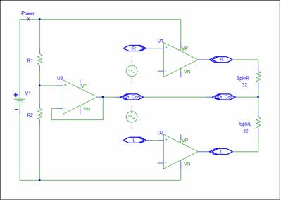
Capacitive Coupled Output
The circuit below returns the output current to the power supply.
In this circuit the midpoint buffer only needs to supply the input bias current, which is very small.
The op-amp outputs are capacitvely coupled to avoid a large DC load on the op-amp and to prevent DC from saturating the Headphones.
Note that the Input common and Output common is NOT the same node. Be careful not to short them.
This is by far the most popular circuit configuration that I found.
I hate it. Here’s why.
- The caps need to be large for good low frequency response.
A 250uF cap has a 32 ohm impedance at 20Hz.
Some brag about the 470uF caps used in their amp.
- The caps create power up and power down transients. The larger the cap the bigger the transient.
The cap needs a DC charge equal to the midpoint voltage, at least 2.5 volts.
On power up the cap needs to be charged.
On power down the cap places 2.5 volts on the output, i.e. an output voltage that is greater than the zero supply voltage.
This is a violation of the Absolute Maximum Rating for most parts. Oops!
- Electrolytic caps are non-linear and physically big.
For best audio quality, Electrolytic caps should not be used in audio circuits.
Some audiophiles have replaced Electrolytic caps in their equipment with higher quality caps.
- The Power On/Off surge current flows thru the headphones.
Although the op-amps limit the surge current, it’s not a good idea to abuse the headphones.
The capacitor surges in this configuration are much worse than in the capacitive rail splitter, because the surge current flows thru the headphones.
If you have a commercial amp with big output caps, you can minimize the this problem, by unplugging the headphones before switching off the amplifier and turning on the amplifier before connecting the headphones. This allows the coupling caps to retain the charge.
The caps block DC from the Headphones. A direct coupled circuit will place a few milli-volts on the headphones.
You could add circuitry to cancel this offset voltage, probably not needed.
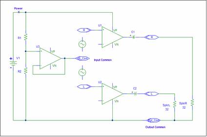
Push Pull
The next configuration uses dual op-amps in a push pull configuration to eliminate the need for output caps.

The second op-amp inverts the output of the first op-amp. When one output goes positive the other will go negative. Since this doubles the output signal, you only need half the supply voltage.
While it’s true that the op-amp sees a 16 ohm load in this push pull circuit, the output current is not changed. You still need 80ma.
The main problem is the headphone connector. Most headphones use a three terminal connector with a common ground. A Push pull output requires two leads per output. If you are willing to cut off the three terminal connector and connect each can to a push pull output, then this is a good option. You can even use the cut off cable as the input cable for the amp.
All the Push pull circuits, that I found, drive the output in a cascade configuration. The second output is created by inverting the first output. The delay thru the amplifier is hence the first op-amp delay plus the second op-amp delay.
Why not apply the input to both amplifiers? In this case the amplifier delay is the single op-amp delay. This will result in a faster slew rate.
The amplifier gains, for 4.5 net gain, are +2.25 and -2.25. A little more complicated, but easily accomplished with Shadow's Design Procedure.
Integrated Charge Pump
A charge pump can be used to create a second supply. The Maxim 9728 contains Op-Amps plus a charge pump.
The part uses an Inverting Amplifier configuration that amplifiers the internal ground noise. This is reflected in the noise specs.
Amplifier Circuit
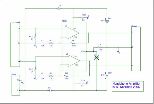
For a prototype, I chose a dual supply circuit. This avoids mid point problems.
If you use a string of batteries with access to the midpoint, you’re making a mistake if you don’t tap the string for the analog ground.
Amplifier Circuit
The amplifier was designed via Shadow’s Design Procedure for a gain of +4.5. The circuit is shown below.
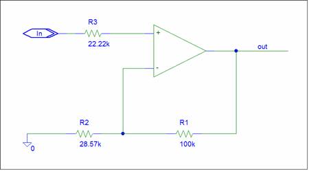
Shadow always creates a balanced circuit. R3 is not needed and can be removed via Ozzie’s Rule . I used 27K for R2.
This creates a gain of 4.7. Close enough to 4.5.
The prototype amplifier circuit is shown below:

R4 was added to create an input load and a bias source for the op-amp.
2K is a compromise value. It can be any value between 32ohms and a meg-ohm. The K9 design value (22k) will create minimum offset.
You don’t want to load down the source, but provide a load in case damping is needed. Selecting an optimum value is too difficult.
I had a lot of 2K resistors.
Analog designers need to add some frequency shaping. Every design needs at least one pole.
C1 was added to create unity DC gain. This prevents the offset voltage from being amplified by the circuit gain (4.7).
C1 needs to be a non-polar cap. You can leave it out if you don’t have a quality cap.
Input Circuit
Virtually all Web circuits use input capacitors. Are these input caps really needed?
My answer is No.
The above design will pass any input DC to the output. I claim there is none.
The MP3 player output needs to provide a 0 volt DC output to the headphones.
Most likely, the player output is capacitvely coupled. There is no need for a second capacitor.
You may want a low pass filter at the input. The input filter and load is important if the input comes from a Class D output.
If high frequency signals are present on the input, they need to be removed. Most op-amps distort high frequency signals and generate audible artifacts. Not Good. Never give an amplifier a signal that it can’t handle.
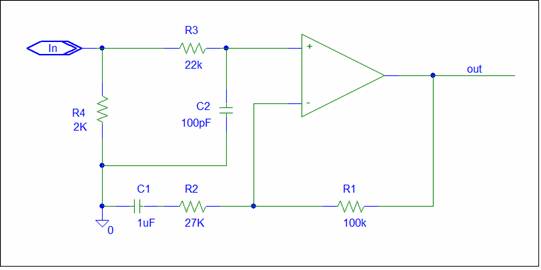
In the above circuit, R3 and C2 form a low pass filter.
R4 provides input loading and bias.
I left the low pass filter out, but kept the input load.
If you leave out the caps, you have an Audiophile dream circuit. No caps in the signal path.
You will need filter caps (0.1uF) for the op-amp supplies.
Batteries
I originally used 4 NIMH AAA cells for the power supply, two for the positive supply and two for the negative supply. This did not produce the desired 50mW output with the TS925. The positive output was clipping. To achieve 50mW output the TS925 needed an extra cell in the positive supply. The positive supply is three cells. The negative supply is two cells. This worked.
In a second amplifier I used two Li-Ion cell phone batteries. They can be expensive if purchased new. I was able to obtain a lot of used batteries via an ebay auction.
Li-Ion batteries typically contain an internal protection circuit to limit surges and overcharging. This circuit will increase the source impedance.
Power Circuit
For a good design, you need to create a design that does not fail. This is especially true for power circuits. The headphone amp power circuit is shown below:
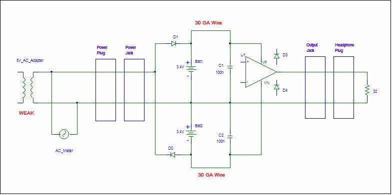
The power circuit needs to provide a low impedance power source to the op-amps. For high frequencies a small capacitor must be connected at the op-amp supply pins. C1 and C2 perform this function. For a DSL op-amp, add additional 10nf caps in parallel with C1 and C2.
Charge the batteries slowly. Rapid chargers require a sophisticated control circuit which may not create a full charge.
I recommend a small AC adapter with an output current of less than 10% of the battery amp/hr rating. For the 900mahr batteries in the prototype, the charger should have no more than a 90ma output. Use a small weak adapter. This implies a long 24hr charging time. The batteries will thank you.
During charging, you can measure the battery voltage by connecting an AC voltmeter across the power input.
Power shorts can occur. I don’t know how, but Murhpy does. Use small 30 gage wire to connect the batteries. The wire can provide a fusible link.
Use different jacks for the audio and power. Don’t assume that this is safe. Murphy will find some way to connect the power to the headphone jack and vice versa.
Diodes D1 and D2 rectify the AC input and prevent the batteries from driving the power jack. When Murphy connects the headphones to the power jack, the diodes block current. Without the diodes, Murphy can damage the headphones.
When Murphy connects the power to the amp output, the weak power supply may save the amp. Most op-amps have protection circuitry on the output. The protection is similar to D3 and D4 in the above schematic. The diodes steer large output voltages to the power supply. If you want to add this protection, use Schotky or Germanium diodes.
Remember you have two options. You can incorporate the protection up front or wait for Murhpy.
Simulation
The simulation circuit is shown below.
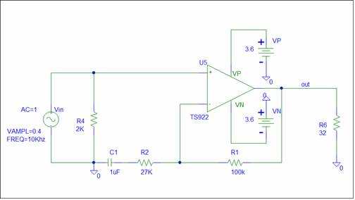
The AC simulation output is
The gain is 4.7. The frequency response is good.
If the low frequency roll troubles you, leave out C1.
The transient response output for a 10Khz input is
The circuit shows no sign of clipping. This is verified by the Fourier output.

Construction
Construction of a prototype requires a lot of time. You need to collect all the parts. Find a case and build.
I used a plastic sample parts case. Metal tins are also popular.
The parts were mounted on a proto board.
The schematic of the prototype is shown below:
The construction schematic using a TS925 is shown below:
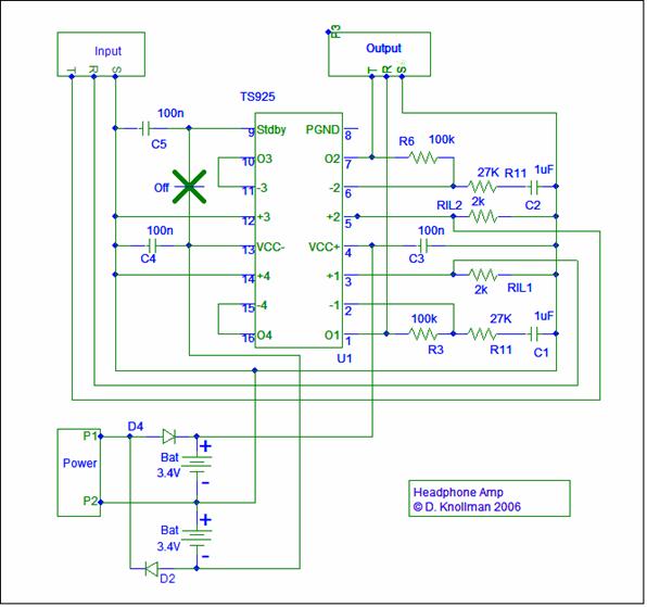
The circuit uses two Li-ion batteries for the power supply.
The power jack is a two pin jack. The battery charging input is via a weak 5 volt AC adapter.
The batteries are charged via D1 and D2.
The input is a 3 pin cable cut from a poor performing headset.
The output is a 3 pin Jack salvaged from an ISA audio card.
T (tip), S (sleeve), and R (ring) denote the physical connections.
For the op-amps I used the TS925. This part has 4 op-amps.
The extra two are wired as buffers with ground as the input. This prevents noise from triggering the unused amps.
The midpoint circuit is not used.
I connected a small switch K1 from the negative supply to the TS925 standby input as an on-off switch.
When closed the circuit goes into a very low current standby mode.
A 0.1uF cap, C5, was added to the Sdby input to minimize internal noise.
Minimize the connection leads to the inverting inputs. Any stray capacitance here is bad.
0.1uF caps were connected to the TS925 at the IC supply pins for filtering.
The batteries are connected to a small 2 pin jack for charging.
Use small gage wire for the battery leads. In case of a problem, they can provide a fusible link.
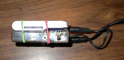
A picture of the prototype is shown below:

The jacks and switches are mounted on the proto board.
The input cable and output jack are on the top.
On-off switch K1 is on the top left.
The power jack is on the bottom left.
There are two batteries. Only one is visible.
The complete portable player is shown below:
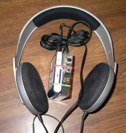
The Amp is mounted below the MP3 player.
Conclusion
The prototype is ugly, but sounds great. There is a noticeable improvement in the audio quality.
I have attempted to discuss the design options for a portable headphone amplifier.
The final design has been optimized by avoiding common audio mistakes such as:
An integrated solution
An input volume control
Output coupling capacitors
Input coupling capacitors
Mid-point bias circuitry
The circuit is simple and ideal. No caps in the signal path.
Less is indeed better.
If you have any comments or questions, send me an email.
I may build a dedicated push pull amplifier next.
The simulation schematic for a single channel circuit is shown below:

The simulation looks good using a single cell phone battery and a TS925.
The layout schematic is shown below:
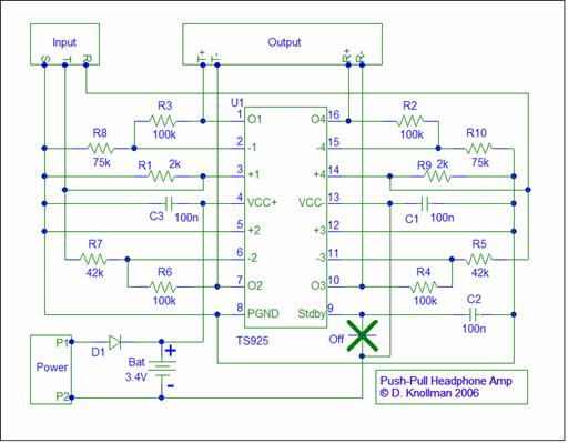
I have not built and tested the Push-Pull amp.
Always look for a picture of the prototype.
Many web designs have never been build and tested.
I may update. If you want to be notified send me an email
Copyright 2006 Dieter Knollman.
The normal disclaimer is:
If anything goes wrong, it’s totally your fault!
|
href="http://www.statcounter.com/"
target="_blank">