K9 Design
Design
is difficult. There are too many things that you need to consider. In
addition to circuit design (Gain, Noise), you need to consider regulatory
requirements (EMI, NEC), Component engineering (Cost, Availability),
Construction (Board layout, Assembly), etc. There are K9 procedures
to address these topics. They don’t meet the 25 word rule. “If you
can’t explain it in 25 words or less, you don’t understand it.” After I
meet the rule, I’ll add them. My only recommendation is: Design it not to
fail.
For the electrical design you
need to consider the power supply voltage, power dissipation, voltages,
currents, etc. Only a small part of Circuit Design is discussed here. In
Legacy Design, you select a circuit and use the design procedure for the
selected circuit. There are different procedures for inverting
amplifiers, non-inverting amplifiers, differential amplifiers, etc.
K9 Design uses a simpler
Design procedure. Instead of selecting a circuit, you only need to specify the
desired gains. Don’t think of your Design in terms of Voltage or
Current. Try to visualize the Design as an Amplifier with an Input, an
Output, and a Gain from input to output. The Gain is the important thing.
A Legacy Inverting Amplifier is an amplifier
with a negative gain.
A Legacy Non-Inverting Amplifier is an
amplifier a positive gain.
A Differential Amplifier is an amplifier with
positive and negative gains of equal magnitude.
Most Legacy circuit can be described in terms
of input to output gains. The general case is a summing amplifier with multiple
gains. The circuit output V(out) is:
V(out) = g1*V1 + g2*V2 + ... +gn*Vn
The gain can be any real or complex
value. Integrators and differentiators are circuits with complex gains.
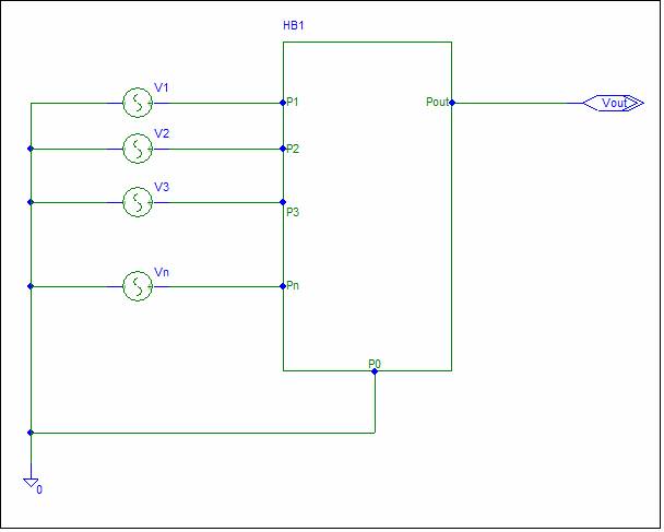
The block diagram can describe any
analog linear circuit.
V1 to Vn are
inputs. They are ideal voltage sources. If your circuit has
non-ideal inputs, the input impedance can be included inside the circuit
block. The gain is always the gain from the ideal input.
The circuit has a Ground Node, and an
Output. A Design element that is often neglected is the gain from the
Ground Node to the Output. You don’t need to specify this gain, but you
may want to minimize the magnitude to reduce ground noise in the output.
After you have determined the gains, use the K9 Noise Reduction Tool before using Shadow's procedure to design the circuit. Everything is very simple. Shadow’s Design Procedure works for all sets of gain, and always designs an optimum circuit containing no more than one op-amp.
Sound too good to be true?
If you have comments or questions send email to k9analysis@netzero.net. If you wonder why the K9 Design Procedure has not been included in Legacy texts, complain to your text author. I have tried without success.