Simple Passive Circuit with Non-Ideal Source
This example applies the VSA procedure to the
Passive Circuit shown below:
![]()
The transfer function from the input nodes to the output node is desired. In this case input 2 is a 600 ohm source. This page shows how to handle a non-ideal source.
Construct General Schematic
The circuit lacks input sources and a ground
node. Assume that the input sources are connected to ground.
The next step is to create a general
schematic. The resistors are replaced with Impedances and the component
values will be dropped.
The circuit is now ready for SFG construction.
SFG Construction
The circuit requires nodes for the input
voltage sources, V1 and V2, and circuit nodes V(i1),
V(i2), and V(out).

V1 and V2 are inputs. The SFG just needs nodes for V1 and V2.
V(i1) and V(i2) are voltage-controlled nodes.
V(i1) = V1 V(i2) = V2
In SFG form
V(i1) = 1 * V1 V(i2) = 1* V2
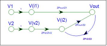
The SFG gets branches from V1 to V(i1) and from V2 to V(i2) with gain equal to one.
The node i2 is a passive summing node. It receives signals from V(v2) and V(out). We will use Brandy’s Gain Formula for node i2. The SFG gain is the Parallel Impedance of the destination node divided by the connecting Impedance, or the destination node impedance divided by the connecting impedance.
Gain fro V(v2) to V(i2) = ZPi2 / ZV2
Gain fro V(out) to V(i2) = ZPi2 / ZV2
ZPi2 =
ZV2 // Z2
The "out" node is also a passive summing node. It receives signals from V(i1) and V(i2).
Gain fro V(i1) to V(out) = ZPout / Z1
Gain fro V(i2) to V(out) = ZPout / Z2
ZPout =
Z1 // Z2
The SFG is complete.
Check the SFG
V1 and V2 are inputs. They not have any incoming branches.
V(i1) and V(v2) are voltage-controlled nodes.
V(i2) and V(out) are a summing nodes. They have incoming branches with gain equal the destination node impedance divided by the connecting impedance.
The SFG has a loop from V(i2) to Vout and back to V(i2). Loops are associated with feedback and the sign of the loop gain specifies the feedback type. In this case the loop gain is positive denoting that the circuit has positive feedback. Can a passive circuit have positive feedback?
Let’s examine the SFG more closely. Input V2 sends a signal to node V(v2). Node V(i2) gets signals from V(v2) and the Vout node. The Vout node sends a signal back to V(i2), because the i2 node impedance, ZP(i2), is not zero. Vout does not send a signal to V(i1) because the ZP(i1) is equal to zero. Brandy’s Gain formula states that the signal gain is the destination node impedance divided by the connecting impedance. If the destination node impedance is zero then the gain is zero.
The loop in the SFG is created by Z2. Z2 is a floating impedance since both ends connect to nodes with non-zero node impedance. An impedance can transmit signals in both directions. The loop models the circulating signals created by the floating node.
Floating impedances create simultaneous equations in the analysis. They make the analysis more difficult, and make the equations more complex. You don’t have to consider this. It’s not on the Final Exam. The VSA answers are always correct, but may not be in the simplest possible form.
Analyze the SFG
The SFG contains one loop from i2 to out and back to i2. The loop gain L is
The loop gain is positive and less than one, since it is the product of two passive circuit gains.
The determinant is: D = 1 – (L)
Since L is less than one, D is not equal to zero. The circuit is stable.
You need to perform this check whenever you have a loop. If D is negative or can be zero, the circuit is probably not stable.
Obtain the gain equation
The circuit has two inputs. We will use Superposition to find the contribution of each input.
For input V1 the SFG contains a single path from V1 to V(out) with gain equal to ZPout / Z1. When the path is removed, there are no loops. The associated D is equal to one.
For input V2, the SFG contains a single path from V2 to V(out) with gain equal to ZPout / Z2. When the path is removed, there are no loops. The associated D is equal to one.
The V(out) formula is created by adding the contributions from each input.

V(out) has two contributions, one from V1 and one from V2. Mason's Gain formula automatically applies superposition. The V(out) / V1 term is the output contribution from the V1 input with the V2 input equal to zero. Substituting the SFG gains yields:
![]()

Check the answer
Opening Z1 should force V(out) to be equal to V2.
Setting Z1 to an infinite value makes the ZPout / Z1 term to zero and the Zpout/Z2 term equal to 1.
![]()
You need to show that 
One way is via lots of algebra. A simpler method is to use Daisy's Theorem and Brandy's Gain formula. The terms represent passive circuit gains at node i2. Daisy's Theorem says that the sum of all the gains at node i2 must be equal to one. There are two gains at i2. The above is just Daisy's theorem applied to node i2.
The SFG does not show the ground gain. You need to check the circuit for Ground Gain whenever you use Daisy's Theorem. In this case i2 has no ground impedance, hence no ground gain.
V(out) is hence equal to V2, if Z1 is open.
Shorting Z1 should force V(out) to be equal to V1. With Z1 = 0, ZPout is equal to zero, and L is equal to zero. The ZPout / Z1 term is 0 / 0 . If you expand ZPout, the ambiguity is resolved to one. V(out) is hence equal to V1.
You can repeat the above for Z2. The analysis is left as a reader exercise.
Output Load
We did not consider the effect of an output load, Zl, in the analysis. Like the previous example, we can repeat the above and arrive at the same SFG. The only difference is that ZPout = Z1 // Z2 // Zl .
This example has illustrated how a non-ideal source can be handled via the VSA procedure. A non-ideal source is likely to create a floating impedance, which creates a loop in the SFG.
|
Circuit |
Signal Flow Graph |
|
|
ZPi2 = RV2 // R2 ZPout = R1 // R2
|
Since the SFG has a
Let’s look at the gain from V1 to V(out). The SFG shows the gain as (ZPout/Z1)/∆. Why is
there a correction? The correction is for ZPout. K9
specifies the node impedance as the parallel combination of impedances
connected at the node. The actual node impedance is R1//(R1+RV2).
The ∆ term corrects for the discrepancy. With a little algebra you can
show that the gain from V1 to Vout is (R1//(R1+RV2))/R1.
The VSA procedure may not have the equation
in the simplest form. You have several options to create a simpler formula.
·
Expand the K9
formula and use algebra.
·
Modify the
circuit model – future
·
Remove the loop
from the SFG - future
For a more difficult example, look at the Ladder example.