Simple Passive Circuit
This example applies the VSA procedure to the
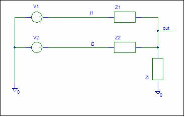
Passive Circuit shown below:
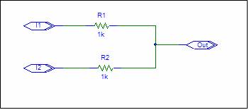
The transfer function from the input nodes to
the output node is desired. You probably don’t need K9 Analysis to solve this
problem. This example illustrates the procedure and some neat features.
Construct General Schematic
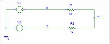
The circuit lacks input sources and a ground
node. Assume that the inputs are ideal
voltage sources connected to ground.
The next step is to create a general
schematic. The resistors are replaced
with Impedances and the component values will be dropped.
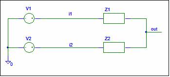
The circuit is now ready for SFG
construction.
SFG Construction
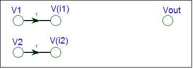
The circuit requires nodes for the input
voltage sources, V1 and V2, and circuit nodes V(i1),
V(i2), and V(out).
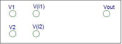
V1 and V2 are inputs. The SFG just needs
nodes for V1 and V2.
V(i1) and V(i2) are a voltage-controlled nodes.
V(i1) =
V1
V(i2) = V2
In SFG form
V(i1) = 1
* V1 V(i2) =
1* V2
The SFG gets branches from V1 to V(i1) and from V2 to
V(i2) with gain equal to one.
The "out" node is a passive summing
node. It receives signals from V(i1) and V(i2). You could write a potential divider equations
for V(out). We will use Brandy’s Gain Formula. The SFG gain is the Parallel Impedance of the
destination node divided by the connecting Impedance.
Gain
fro V(i1) to V(out) = ZPout
/ Z1
Gain
fro V(i2) to V(out) = ZPout
/ Z2
ZPout =
Z1 // Z2
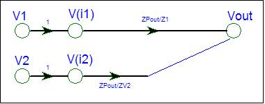
The SFG is complete.
Check the SFG
V1 and V2 are inputs. They not have any
incoming branches.
V(i1) and V(i2) are voltage-controlled nodes.
V(out) is a summing node. It has incoming branches with
gain equal the parallel impedance of the destination node divided by the
connecting impedance.
The SFG shows signal flow from both inputs to
Vout.
Analyze the SFG
The SFG contains no loops. The determinant is
hence equal to one.
D = 1
The circuit has two inputs. We will use Superposition to
find the contribution of each input. Superposition requires that you set the
other inputs equal to zero. Voltage source inputs are replaced by a short. The SFG does this for you automatically. There is no need to consider a different
circuit for each input. Multiple inputs are never a problem. You do need to
remember that K9analysis assumes Superposition and automatically replaces other
voltage inputs with a short.
For input V1 the SFG contains a single path
from V1 to V(out) with gain equal to ZPout / Z1.
Gain
from V1 to V(out) = V(out) / V1 = ZPout
/Z1
The gain from V1 to V(out)
with other inputs equal to zero is written as V(out) / V1. In this case V2 has been replaced by a
short. This is was
done automatically by the VSA procedure.
For input V2, the SFG contains a single path
from V2 to V(out) with gain equal to ZPout / Z2.
Gain
from V2 to V(out) = V(out) / V2 = ZPout
/ Z2
The V(out) formula
is created by adding the contributions from each input.
V(out) =
(V(out) / V1) * V1 + (V(out) / V2) * V2
V(out) = ZPout / Z1 * V1 + ZPout / Z2 *
V2
Check the answer
Opening Z1 should force V(out)
to be equal to V2. Setting Z1 to an
infinite value makes the ZPout / Z1 term to zero and
makes ZPout equal to Z2. V(out) is equal to
V2.
Shorting Z1 should force V(out)
to be equal to V1. With Z1 = 0, ZPout is equal to zero.
The ZPout / Z1 term is 0 / 0
. If you expand ZPout, the ambiguity is
resolved to one. V(out)
is hence equal to V1.
You can repeat the above for Z2.
Output
Load
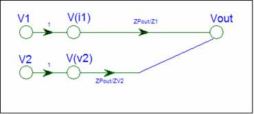
We did not consider the effect of an output
load in the analysis. Let’s add a load
impedance Zl to the output.
We can repeat the above and arrive at the SFG
shown below.
Note that the SFG has not changed. The only difference is that ZPout = Z1 // Z2 // Zl .
If you use the VSA procedure to construct the
SFG, adding an impedance to ground at a node does not
change the SFG. This feature is handy if
you want to evaluate the effect of stray capacitance at a node. Instead of complicating the analysis, just
include the stray impedance term when calculating the ZP term.
For maximum utility, don’t expand ZP
terms. You can add ground impedances to
the schematic without affecting the VSA created SFG. This may not be true if
you use a different procedure.
This example illustrated how the VSA
procedure handles superposition automatically and that ground impedances do not
change the SFG.
|
Circuit |
Signal
Flow Graph |
|
|
ZPout =
Z1 // Z2 // Z3 V(out)
= ZPout / Z1 * V1 + ZPout
/ Z2 * V2 |
The SFG has no loops, the path gains are the circuit
gains. You need to add the contributions from each input to create the output
equation.
This circuit with a non-ideal source is
analyzed on the Passive Circuit with Non-Ideal Source
page.
For a more difficult example, look at the Ladder example.