Ladder Output Impedance
There was a miscommunication. The output impedance, not the input impedance, is required. Even though this rarely happens, K9 Analysis can provide a solution.
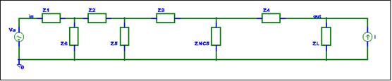
The approach in this case is a little different. We will add an input to derive an equation for the output impedance. A current source, I, connected to the output will allow the output impedance to be calculated via the transfer function from I to Vout.
Zout = Vout / I
Think of I as a test
current. When you want to find a node impedance,
connect a 1 amp current source and see how much voltage is developed.
Don’t try this on a real circuit. It only works for linear circuit analysis
and AC simulations. Let the fireworks begin.
The general schematic with the current source
is shown below.
The gain from a current source to a summing
node is the parallel impedance of the node. If the current flow into the node
the gain is positive; if it flows out of the node the gain is negative. The
modified SFG is shown below.

Analyze the SFG
The I node did not add any loops to the SFG. From the Ladder analysis
L1 = ZP2/Z2 * ZP1/Z2
L2 = ZP3/Z3 * ZP2/Z3
L3 = ZPout/Z4 * ZP3/Z4
L1 and L3 are non-touching loops.
The determinant is:
D = 1 + (L1 + L2 + L3) + (L1 * L3)
When calculating the gain from I to Vout, we will use Superposition and set Va equal to zero.
There is one path from I to Zout. This path touches only L3. The associated delta for this path is:
D3 = 1 + (L1 + L2)
The transfer function is.
Zout = Vout / I = (ZPout* D3)/D
Check the Answer
If Z4 is opened, the output impedance should be equal to Zl.
With Z4 infinite, ZPout will be equal to Zl and L3 will be equal to zero. With L3 equal to zero, D3 will be equal to D. Zout is hence equal to ZL if Z4 is equal to zero.
Conclusion
This example illustrated how to add a test
current to allow the equation for a node impedance to be derived.
Adding a test current is an easy way to
measure the impedance of a node. A
current source has high impedance and will not alter linear circuit operation.
No loops are added to the SFG. You can use this trick in an AC simulation. It
is difficult to implement on a real circuit.
ZPout is the output impedance if there are no circuit
interactions. The ∆ terms provide the corrections. ∆ compensates
for the entire circuit. ∆3 is needed to cancel the compensation for the
non-touching loops.
Summary
You can use the test current trick on any
node. The K9 node impedance may need a correction for circuit interactions
(loops).
You can extend the analysis to larger latter
networks. Note that only the ∆ terms change.
You can expand on the concepts described in this
ladder example to find general circuit equations. The idea behind K9 is not to
analyze a single specific circuit. It is actually easier to derive the gain
equation for a class of circuits. Who said that analog circuits are difficult?
The telephony guys may want an equation for
the two wire insertion
loss of the ladder circuit. Reader exercise.
In the next example we will derive the
general gain equation for many single op-amp circuits.