K9 Analysis
The intent of K9 Analysis is to make Analog
Circuit Analysis Dog Gone Simple. If you like complex math procedures, K9
Analysis is not for you. K9 Analysis circumvents the need for calculus, complex variables, simultaneous
equations, and matrices. This
is accomplished by using Impedances and Signal Flow Graphs
(SFG).
The analysis consists of constructing a
Signal Flow Graph from a circuit schematic and then using Mason's Gain Formula to
write the desired equations. SFGs are normally
constructed from a block diagram or a set of equations. The SFG depends on the
equations used to define a SFG variable and hence is not unique. Since a SFG
may not clearly describe circuit operation, they are not used in Electronics.
K9 creates an intuitive circuit description
by constructing the SFG from the circuit schematic. Signals propagate from
input to output thru circuit components. The signal flow becomes the circuit
description.
Circuit analysis often consists of a circuit
with an input, Vin, an output, Vout, and a transfer
function, g,
|
Circuit
Schematic |
Equation |
Signal
Flow Graph |
|
|
Vout
= g Vin |
|
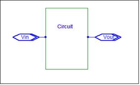
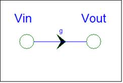
A circuit can be a schematic, a set of
equations, or a signal flow graph.
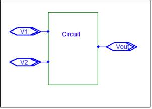
For two inputs:
|
Circuit
Schematic |
Equations |
Signal
Flow Graph |
|
|
Vout
= g1*V1 +g2*V2 |
|
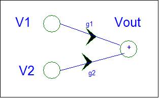
The SFG nodes represent the circuit node voltages.
A SFG node is a summer. It adds the signals from incoming branches.
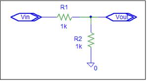
For a simple circuit:
|
Circuit |
Equations |
Signal
Flow Graph |
|
|
Vout
= ½ Vin |
|
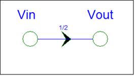
Wouldn’t it be nice
if all circuits were this simple? The intent of K9 analysis is to make every
circuit as simple as the above example. Well almost.
Most circuits are
not as simple as the above example because they have many components that
interact. This complicates Electronic analysis. There are many ways to handle
the interaction. Remove the interaction by a circuit trick, solve the
simultaneous equations created, or handle the interactions via corrections.
The typical
Electronics analysis approach is to sequentially collapse the circuit to a
simpler form. Electronics uses a set of circuit tricks to simplify
analysis. The Legacy
page describes the Op-amp circuit analysis trick. The page also shows that this
trick can fail when applied to a different op-amp circuit.
K9 Analysis uses a
different approach. The circuit is modeled under the assumption that there is
no interaction. When interaction occurs, correction factors are applied. The K9
VSA procedure creates a SFG from the circuit schematic. The SFG is created incrementally.
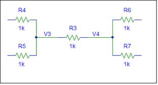
For a resistor, the SFG has two branches
because the resistor can propagate signals from V3 to V4 and from V4 to V3. The
gains are obtained from Brandy’s Gain Formula.
|
Circuit |
Signal
Flow Graph |
|
|
|
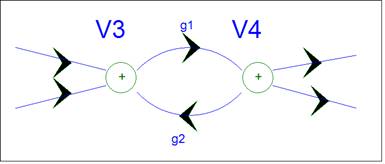
The “+” in the SFG symbol was added to
emphasize the sum operation performed. The normal SFG node symbol is a dot.
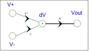
For an op-amp, the SFG is created from the
op-amp equations.
|
Circuit |
Equations |
Signal
Flow Graph |
|
|
dV = V+
- V- Vout
= A * dV |
|

The Voltage Signal Analysis (VSA) procedure makes voltage
the primary circuit variable. The
procedure is based on Nodal Analysis
. In VSA each SFG node is a node equation. This allows an easy transformation
of a circuit schematic into a SFG. The node equations are well hidden. There is a SFG node for each circuit node, except the
ground node. The SFG node is the voltage at the circuit node with respect to
the ground node. The SFG does not contain a ground node because the ground
voltage is zero volts and hence can not contribute to other nodes.
Circuit equations
only depend on the circuit topology. K9
Analysis uses Impedance for passive circuit components. There is no distinction between resistors,
capacitors, or inductors. The component
values are also dropped. This allows a simple derivation of a circuit equation
without the need for calculus or complex variables.
Modeling components
as Impedances also allows a more accurate analysis. You can use actual
impedance values when evaluating equations. You can add stray components. In
VSA, you can even add load impedances.
Each circuit node
has a Node Impedance which is the parallel combination (ZP) of the impedances
connected at the node. The Node Impedance is the circuit Impedance to ground,
if all connecting impedances have ground at the other end. If a grounded
voltage source is connected to a node, the parallel impedance is equal to zero
and the node is called a voltage controlled node.
In a circuit, the nodes are connected via
Impedances. Each node is affected by the
nodes that it is connected to. In the
SFG the effect is modeled by a branch.
The branch gain is the local circuit gain, if the connecting impedances
are grounded. This creates simple branch gains. When a branch connects to
another node with a non-zero node impedance, the
simple branch gain formula needs a correction. The K9 approach is : Write simple equations and let the SFG provide a
correction if needed.
Circuit operation
is described by equations. Circuits have
inputs of known value and one or more outputs. If the circuit has an output,
Vout, that depends on two inputs, V1 and V2, the equation is:
Vout = f(V1, V2)
There is some
equation that describes how to get the output voltage if the input voltages are
known. For a linear circuit, Vout can be described by the linear equation:
Vout = g1 * V1 + g2 * V2
K9 is restricted to
linear circuits. All equations are in
the above linear format. The output is the sum of gains times
inputs. The circuit adds the contributions of each input to create the output
value. Any linear circuit is hence a
summing circuit.
The circuit
operation is described via input to output gains. If the circuit is linear, Superposition
applies. You can analyze each input separately.
In Electronics this requires a separate circuit for each input. In K9
this is done automatically. Multiple inputs cause no problems. There is one circuit and one SFG.
For most circuits,
the input to output gain is not obvious.
You need to analyze small sub-circuits and create a set of equations.
There are many ways to do this. If you are clever, the equations can be easy to
solve. This is the intent of Electronic
circuit tricks.
VSA uses the
circuit node voltages as variables. Each
circuit node, that is not an input, requires a defining equation. You enter the
defining equation for each node into the SFG. The equation describes how the
circuit creates the node voltage. If the node impedance is zero, the node is
controlled via voltage sources. You need to enter an equation which specifies
how the node is controlled by the voltage source(s). If the node impedance is not zero, then the
node is connected via impedances to other nodes. In this case, each impedance contributes to the node voltage (nodal
equation). The SFG node will receive an incoming branch for
each impedance. The branch gain is specified via Brandy’s
Gain Formula.
A SFG can have
multiple inputs and be used for the entire circuit. Via small additions the SFG
can be used to obtain equations for input impedance, output impedance, etc. A
single SFG can handle the entire circuit analysis.
After the SFG is
constructed, Mason’s Gain
Formula is used to obtain the input to output circuit gain, which is the
path gain thru the SFG. If a SFG has multiple paths, you simply add the path
gains.
Circuits can have
interactions (feedback) that alter the path gain. Circuit interaction is
displayed by Loops in the SFG. Mason’s Gain Formula
handles the interaction in two ways. Each equation has a denominator ∆
term that corrects for all circuit interactions. This correction is the same for all gains.
Some paths in the SFG may not be affected by all interactions. In this case a
numerator ∆ term is added. The numerator term contains only loops that
are not touched by the path.
The denominator
term can be analyzed for circuit stability.
If ∆ can be equal to zero, the circuit is not stable.
Electronics
associates Loops with Feedback. There
are many different types of feedback.
The discussion can be very confusing.
I’m not comfortable with the distinctions. In many cases, feedback is created by the equations
used. It may not be a circuit property. Don’t worry about feedback. The SFG
will tell you if Feedback is present. It’s handled automatically.
Consider the
Resistor example shown above. In the circuit, R3 is connected between node V3
and V4. The SFG has branches between V3 and V4 to allow signal transmission in
both directions. This creates a loop. Since the loop gain is positive, R3
creates positive feedback in the circuit. There is no danger of instability.
The
The VSA procedure
creates Loops only when needed. If one node of an impedance is connected to a
voltage controlled node, then the impedance can not affect the voltage at that
node. In this case there is no branch via the impedance to the node. Also if a component is redundant, it will not
show up in the SFG. The procedure does this automatically.
Another benefit of
the SFG is that it is a simple intuitive circuit description. The SFG created via VSA shows the paths of
signals from input to output. Most engineers can understand the SFG.
K9 Analysis makes
circuit analysis Dog-Gone-Simple by using a Signal Flow approach to Electronic
Circuits. A circuit is described by a schematic. The rules for an analysis
schematic are discussed on the Schematic page. Signal
Flow is discussed on the Signal Flow page. The
SFG is discussed on the Signal Flow Graph page.
You can skip these pages. Scan the VSA procedure
below and let the examples illustrate the K9 procedure.
VSA Procedure
The K9 Voltage Signal Analysis (VSA)
procedure for obtaining circuit equations is outlined below. Just scan the
steps. The examples will illustrate the procedure.
Edit the circuit schematic – create a general
schematic
Replace passive components with Lumped Impedances.
Model active components as controlled sources.
Convert floating voltage sources to current sources.
Add inputs to stimulate the circuit, and loads not
included in the original circuit.
Label all circuit nodes.
Construct a Signal Flow Graph
Add a SFG node for each input, circuit node, and
controlled source input and output.
For each SFG node that is not an input node, add
branches to define the node variable.
Check the SFG.
Use Mason’s Gain Formula to
extract the desired equations.
Find the Loops in the SFG.
Write the system determinant. D = 1 - å loops + å loop pairs – etc.
For each output find the path gain from all inputs.
Write the desired equations.
Check the answer via shorts and opens.
The VSA procedure
differs from legacy circuit analysis in the following ways:
The use of Impedances provides a more general analysis
and eliminates the need for calculus, complex variables, and numeric
calculations in the derivation of gain equations.
The Analysis allows accurate impedance models. If lead
inductance or stray capacitance is significant, you can add these parameters
when evaluating the equations.
Controlled sources are easily accommodated. They are
easier to model on a SFG than a passive impedance. Controlled sources propagate
signals in a single direction. Passive Impedances are bi-directional.
Multiple inputs allow a single K9 analysis to produce
many circuit equations. Superposition is implied. Most circuits require only a
single SFG to extract all equations.
The SFG provides a circuit description that is easily
comprehended by most engineers.
Mason’s Gain formula eliminates the need for
simultaneous equations or matrices.
Circuit reduction to eliminate feedback is not
required. You only need to model the local effects at a circuit node; the SFG
will handle the global effects. The SFG will tell you when feedback is present
in your circuit.
The main disadvantage of VSA is its
simplicity. You can easily derive circuit equations that are too big to handle.
With VSA analysis there are no difficult circuits, just big answers.
Test K9 Analysis via the following examples.
Each example illustrates a feature of VSA.
Simple Amplifier Circuit – an introduction to VSA.
Simple Passive Circuit – multiple
inputs
Simple Passive Circuit with Non-Ideal Source
– a non-ideal input
Ladder
Circuit – demonstrate the power of K9 Analysis.
General Summing Circuit - Plato’s Gain Formula.
Two Op-amp Summing Circuit – Legacy Summing Amplifier
State Variable Filter – Use Plato’s Gain
Formula in SFG
Future additions:
Series
Impedance Lump – Reduce Loops, simplify equations
Ad
Hoc Analysis – Combine Voltage and Current equations
Discrete
Circuit Examples – Current as main Variable
Controlled
Sources – Transistor models
I may add more examples in the future. If you
would like to be notified when new material is added send an email to k9analysis@netzero.net with update as the subject.