Legacy Op-Amp Analysis
The Op-Amp circuit analysis as described in most text books,
uses the following Procedure:
· The Op-Amp is assumed to be
ideal.
o
The gain is infinite.
o
The input impedance is infinite.
o
The output impedance is zero.
· The differential input voltage
is equal to zero.
o
The large gain requires a very small input to yield a finite output.
The infinite op-amp gain will create an infinite output voltage for any
input that is not zero. For a finite output, the differential input voltage
must be equal to zero. This means that both input terminals must have the same
voltage. If the circuit has one of the inputs connected to ground, then the
other input must have ground potential. This node is called a Virtual Ground.
Let's use this technique to analyze two circuits.
Inverting Amplifier
The schematic of an inverting amplifier is shown below.
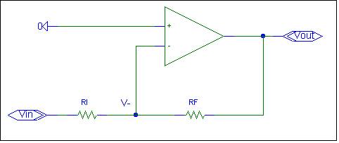
The (+) op-amp input is connected to ground. Since the op-amp has large
gain, the differential input voltage needs to be zero. The voltage at the (-)
op-amp input, V-, must also be zero. To
simplify analysis, we will assume that V- is at ground potential.
Assume V- = 0.
When we apply an input to Vin, current will flow
thru RI. Due to infinite op-amp input impedance, no current flows into the
op-amp inverting input. All the current
from Vin must flow thru RI and RF to Vout. Since V- is equal to zero, the current is
equal to
I = Vin
/RI
And to allow the same current to flow thru RF, Vout must equal
Vout = - RF * I
Substituting for I yields:
Vout = - RF * Vin / RI = - RF /RI * Vin
The gain of the inverting amplifier is - RF / RI.
To complete the derivation, we need to verify the assumption that V- is
equal to zero.
With Vout = - RF/RI * Vin, the voltage V- is
equal to zero. Reader
exercise.
The assumption is verified and the result proven.
The analysis is simple and elegant.
Let's try another circuit.
Trial Amplifier
The schematic is shown below:
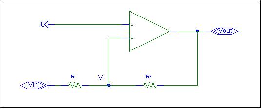
The circuit is similar to the inverting amplifier, except the Op-Amp
inputs are reversed. Is it possible to
create a non-inverting amplifier by simply reversing the Op-Amp inputs? Let's analyze the trial amplifier circuit
with Legacy analysis to find the circuit gain. The analysis is the same as the
inverting amplifier.
With infinite op-amp gain, the differential op-amp input voltage must be
equal to zero to create a finite output voltage. The voltage at the inverting
input (V-) must be equal to zero since the inverting input is grounded.
Assume V- = 0.
Due to infinite input impedance, no current flows into the op-amp
non-inverting input. All the current
from Vin must flow thru RI and RF to Vout. Since V- is equal to zero, the current is
equal to
I = Vin
/RI
And to allow the same current to flow thru RF, Vout must equal
Vout = - RF * I
Substituting for I yields:
Vout = - RF * Vin / RI = - RF /RI * Vin
Hence the gain of the Trial circuit is - RF / RI.
To complete the derivation, we need to verify the assumption that the
differential input voltage is equal to zero.
With Vout = - RF/RI * Vin, the voltage V- is
equal to zero. Reader exercise.
The circuit is an inverting amplifier, not the non-inverting amplifier
hoped for. Is this really another form of inverting amplifier? Legacy analysis
would suggest that the Trial circuit is an inverting amplifier.
If you build and test the circuit, you will discover that the output
(Vout) is stuck at a supply rail. If you
force the condition where Vout = -RF/RI * Vin, the V-
voltage will be equal to zero. The
circuit however does not like to maintain this state. Any disturbance will cause the output to
switch to a supply rail.
What's wrong?
Mathematically, the analysis is correct.
In both cases we made an assumption and verified the assumption. In both cases the derived formula meets all
circuit equations. There is nothing wrong with the math.
The problem is that the analysis failed to check for stability. Stability is normally checked via the
system determinant. The “elegant”
procedure avoided simultaneous equations and the need to calculate the system
determinant. Finding a solution is not sufficient. You need to verify that the
solution is stable.
Virtual Ground
In the analysis, one input was grounded.
If the differential op-amp input voltage is zero, the other op-amp input
must be at ground potential, hence the name Virtual Ground.
Don’t confuse Virtual
Ground with circuit ground. Virtual ground is a concept,
circuit ground
is a reference node.
Don’t confuse circuit ground with earth ground. The circuit ground node
does not have to be connected to earth ground. The circuit ground node is
simply a node in the circuit that has been selected to be the reference node
for voltage measurements.
The Virtual Ground concept is also used for a Current
to Voltage converter. In this
circuit the Virtual Ground is the circuit input. There are many problems with this concept.
First, the name is misleading, it may not be ground. What’s important is that the differential
input voltage is zero. In the case of a non-inverting
amplifier, the analysis is similar, except V- is equal to the non-inverting
input voltage.
Ground implies a low impedance node.
In many circuits, large currents flow thru the ground node. In hostile environments, large signals are
often intentionally diverted to ground. Ground is a very robust node. The
virtual ground has totally opposite properties.
It is usually the most sensitive node in an op-amp circuit. Just
touching the Virtual Ground can create instability.
A Virtual Ground
implies a ground potential. Connecting a component from a Virtual Ground to
circuit ground, should have no effect on circuit operation. There is no voltage
difference and no current will flow. This is what Legacy implies. Don’t believe
this.
Any input should be expected to have some capacitance. Analogue gurus
know that capacitance to ground at the Virtual Ground can
create instability. The op-amp has a 90°
phase shift. The feedback resistor plus Virtual Ground capacitance creates
another 90° phase shift and possible instability. Legacy texts ignore this hazard.
To test the Virtual Ground concept, let’s simulate an inverting amplifier
with a gain of -1. A Human
Body Model circuit has been added to simulate a person touching the op-amp
inputs. The HBM circuit consists of a 100pF capacitor in series with a 1.5K
resistor. In the circuit below, the HBM is R3 + C1 and R7 + C2.
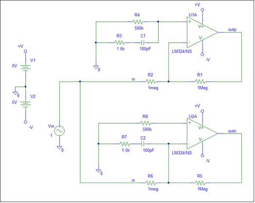
In the top circuit, the person is touching the (+) op-amp input. In the
bottom circuit, the person is touching the (-) op-amp input. The Virtual Ground
concept makes both op-amp input voltages equal to zero. Since both ends of HBM
are at ground potential, there should be no current in the HBM circuit. With
zero current, the HBM circuit should not affect op-amp circuit operation.
Let’s test this via an AC simulation. Both circuits have a 1 volt AC
input. The simulation output is shown below:
The output of the top circuit is shown in the red plot. The output
magnitude is one. This is what is expected. The green plot shows the output
when the HBM is connected to the Virtual ground. Note the output voltage spike
at 30khz.
The simulation output shows a voltage greater than the supply voltage.
How is this possible? The AC simulation
calculates an operating point for the circuit and then assumes linear behavior.
In linear operation, any voltage is possible. What the large output means is
that the circuit is probably not stable. When I tried a transient simulation,
the simulator failed to converge; another sign of an unstable circuit.
If you want to test this concept on a real circuit, hold one hand at a
ground node while touching an input. You may have thousands of volts stored
which can cause op-amp damage. You need to have one hand connected to ground at
all times.
Using any op-amp node as an input is not recommended. This is especially
true for a Virtual Ground node.
Plato says “ Don’t
probe the (-) input. It’s ok to probe the (+) input ”.
Virtual Ground implies that it’s ok to probe either input, since no current
will flow in the probe.
You decide who is correct.
Electronics uses the Virtual Ground concept to derive op-amp equations.
Since the formulas are correct, the analysis appears valid. Oliver Heaviside said
“Since the answers can always be verified, it is un-important how they are
obtained.” The key term is verified. It’s ok to use Virtual Ground for
“elegant” gain formula derivation. It’s not ok to hide the circuit hazard that
is created.
Look at the Stability page for a K9
explanation.